Page 3 of 16 FirstFirst 12345678910111213 ... LastLast
Results 41 to 60 of 302

Thread: LG TV wipeout

  1. #41
    Premium Member
    Skepticist's Avatar
    Join Date
    Apr 2009
    Posts
    1,139
    Thanks
    714
    Thanked 670 Times in 525 Posts
    Rep Power
    475
    Reputation
    12780

    Default

    That'll certainly save a lot of time for targeted hands-on probing

    Check for 400V (approx) on Q101, if there's none then LB106 is likely to be open circuit - the fault current that destroyed the fuse and FETs went through there.
    Last edited by Skepticist; 20-07-17 at 12:06 AM.

  2. The Following User Says Thank You to Skepticist For This Useful Post:

    loopyloo (26-07-17)


  • #42
    Premium Member

    Join Date
    Jan 2008
    Posts
    4,311
    Thanks
    5,982
    Thanked 4,171 Times in 1,771 Posts
    Rep Power
    1349
    Reputation
    50392

    Default

    To satisfy my curiousity, what is the model number of the television receiver.

    The thread title suggests it's an LG, but which model?

    (I couldn't see it mentioned elsewhere in the thread)

  • The Following User Says Thank You to tristen For This Useful Post:

    loopyloo (26-07-17)

  • #43
    Senior Member
    loopyloo's Avatar
    Join Date
    Feb 2008
    Location
    Mid North Coast NSW . Australia
    Age
    67
    Posts
    2,208
    Thanks
    1,431
    Thanked 470 Times in 314 Posts
    Rep Power
    416
    Reputation
    7317

    Default

    I found a diagram for it but it's near impossible to read :

  • #44
    Member tw2005's Avatar
    Join Date
    Oct 2010
    Location
    Mancave
    Posts
    308
    Thanks
    51
    Thanked 114 Times in 84 Posts
    Rep Power
    209
    Reputation
    1743

    Default

    Quote Originally Posted by loopyloo View Post
    I found a diagram for it but it's near impossible to read :
    Same image I posted. If you want bigger, search the board number EAY62512701 and download the engineering document in PDF, then you can blow it up as big as you like.


  • The Following User Says Thank You to tw2005 For This Useful Post:

    loopyloo (25-07-17)

  • #45
    Senior Member
    loopyloo's Avatar
    Join Date
    Feb 2008
    Location
    Mid North Coast NSW . Australia
    Age
    67
    Posts
    2,208
    Thanks
    1,431
    Thanked 470 Times in 314 Posts
    Rep Power
    416
    Reputation
    7317

    Default

    Quote Originally Posted by tristen View Post
    To satisfy my curiousity, what is the model number of the television receiver.

    The thread title suggests it's an LG, but which model?

    (I couldn't see it mentioned elsewhere in the thread)
    Ah yeah, Looks like that slipped my mind.
    It's a 47LM6200 smart.

  • The Following User Says Thank You to loopyloo For This Useful Post:

    tristen (20-07-17)

  • #46
    Senior Member
    loopyloo's Avatar
    Join Date
    Feb 2008
    Location
    Mid North Coast NSW . Australia
    Age
    67
    Posts
    2,208
    Thanks
    1,431
    Thanked 470 Times in 314 Posts
    Rep Power
    416
    Reputation
    7317

    Default

    Quote Originally Posted by tw2005 View Post
    Same image I posted. If you want bigger, search the board number EAY62512701 and download the engineering document in PDF, then you can blow it up as big as you like.

    Lol ... Didn't see your post and you were quicker than me to post it.
    That's awesome. Thanks. I couldn't find anything like that.
    I'll download it right away.

  • #47
    Senior Member
    loopyloo's Avatar
    Join Date
    Feb 2008
    Location
    Mid North Coast NSW . Australia
    Age
    67
    Posts
    2,208
    Thanks
    1,431
    Thanked 470 Times in 314 Posts
    Rep Power
    416
    Reputation
    7317

    Default

    Quote Originally Posted by Skepticist View Post
    That'll certainly save a lot of time for targeted hands-on probing

    Check for 400V (approx) on Q101, if there's none then LB106 is likely to be open circuit - the fault current that destroyed the fuse and FETs went through there.
    125v on all fets

  • #48
    Premium Member
    Skepticist's Avatar
    Join Date
    Apr 2009
    Posts
    1,139
    Thanks
    714
    Thanked 670 Times in 525 Posts
    Rep Power
    475
    Reputation
    12780

    Default

    400V was a major over-estimation (it was late when I posted that), should be around 340V across the large cap (120uF 450V).
    An average of about 170V across each inverter FET would indicate they are actually running (switching alternately at high speed) and yet there's no 12V or 24V output?

    Got me thinking about C114 (18nF 800V) if the FETs are switching but so many possibilities need a lot more data to narrow it all down.
    Last edited by Skepticist; 20-07-17 at 02:06 PM.

  • The Following User Says Thank You to Skepticist For This Useful Post:

    loopyloo (25-07-17)

  • #49
    Premium Member

    Join Date
    Jan 2008
    Posts
    4,311
    Thanks
    5,982
    Thanked 4,171 Times in 1,771 Posts
    Rep Power
    1349
    Reputation
    50392

    Default

    Quote Originally Posted by loopyloo View Post
    Ah yeah, Looks like that slipped my mind.
    It's a 47LM6200 smart.
    You will find the complete service manual for that at .

    The manual appears to contain relevant circuit diagrams.

    The parent url is .

    Some members might remember that I have mentioned the jordansmanuals website in past threads.

    Loopy, I suggest that you write it on the back of your workshop door for future reference.

  • The Following User Says Thank You to tristen For This Useful Post:

    loopyloo (20-07-17)

  • #50
    Senior Member
    loopyloo's Avatar
    Join Date
    Feb 2008
    Location
    Mid North Coast NSW . Australia
    Age
    67
    Posts
    2,208
    Thanks
    1,431
    Thanked 470 Times in 314 Posts
    Rep Power
    416
    Reputation
    7317

    Default

    Quote Originally Posted by tristen View Post
    You will find the complete service manual for that at .

    The manual appears to contain relevant circuit diagrams.

    The parent url is .

    Some members might remember that I have mentioned the jordansmanuals website in past threads.

    Loopy, I suggest that you write it on the back of your workshop door for future reference.
    Lol yeah...I put it in favorites

  • #51
    Senior Member
    loopyloo's Avatar
    Join Date
    Feb 2008
    Location
    Mid North Coast NSW . Australia
    Age
    67
    Posts
    2,208
    Thanks
    1,431
    Thanked 470 Times in 314 Posts
    Rep Power
    416
    Reputation
    7317

    Default

    Quote Originally Posted by Skepticist View Post
    400V was a major over-estimation (it was late when I posted that), should be around 340V across the large cap (120uF 450V).
    An average of about 170V across each inverter FET would indicate they are actually running (switching alternately at high speed) and yet there's no 12V or 24V output?

    Got me thinking about C114 (18nF 800V) if the FETs are switching but so many possibilities need a lot more data to narrow it all down.
    What is L601 ? Is it a transformer ? or maybe for current sensing or something ?

  • #52
    Premium Member
    Skepticist's Avatar
    Join Date
    Apr 2009
    Posts
    1,139
    Thanks
    714
    Thanked 670 Times in 525 Posts
    Rep Power
    475
    Reputation
    12780

    Default

    It's part of the power factor correction system. If you're reading a full 340V across C610 it's not interfering with the supply enough to cause a problem.
    The standby 3.5V supply runs off the same bus and it's fine, it also supplies the Vcc to the PFC and the inverter controllers.

  • The Following User Says Thank You to Skepticist For This Useful Post:

    loopyloo (26-07-17)

  • #53
    Member tw2005's Avatar
    Join Date
    Oct 2010
    Location
    Mancave
    Posts
    308
    Thanks
    51
    Thanked 114 Times in 84 Posts
    Rep Power
    209
    Reputation
    1743

    Default

    Quote Originally Posted by loopyloo View Post
    What is L601 ? Is it a transformer ? or maybe for current sensing or something ?
    will be a coil for filtering, will be pretty obvious on the board

  • The Following User Says Thank You to tw2005 For This Useful Post:

    loopyloo (26-07-17)

  • #54
    Senior Member
    loopyloo's Avatar
    Join Date
    Feb 2008
    Location
    Mid North Coast NSW . Australia
    Age
    67
    Posts
    2,208
    Thanks
    1,431
    Thanked 470 Times in 314 Posts
    Rep Power
    416
    Reputation
    7317

    Default

    Quote Originally Posted by tw2005 View Post
    will be a coil for filtering, will be pretty obvious on the board
    ha ha wasn't so obvious to me,that's why I asked lol

  • #55
    Member tw2005's Avatar
    Join Date
    Oct 2010
    Location
    Mancave
    Posts
    308
    Thanks
    51
    Thanked 114 Times in 84 Posts
    Rep Power
    209
    Reputation
    1743

    Default

    Quote Originally Posted by loopyloo View Post
    ha ha wasn't so obvious to me,that's why I asked lol
    Generally L designates an inductor or coil, T transformer

  • The Following User Says Thank You to tw2005 For This Useful Post:

    loopyloo (26-07-17)

  • #56
    Senior Member
    loopyloo's Avatar
    Join Date
    Feb 2008
    Location
    Mid North Coast NSW . Australia
    Age
    67
    Posts
    2,208
    Thanks
    1,431
    Thanked 470 Times in 314 Posts
    Rep Power
    416
    Reputation
    7317

    Default

    Quote Originally Posted by tw2005 View Post
    Generally L designates an inductor or coil, T transformer
    Yes that's right, but not all may be as it seems.
    And yes C for cap, R for resistor, U for whoops! chip?, F for fuse, and so on.
    Try this one then :


  • #57
    Premium Member
    Skepticist's Avatar
    Join Date
    Apr 2009
    Posts
    1,139
    Thanks
    714
    Thanked 670 Times in 525 Posts
    Rep Power
    475
    Reputation
    12780

    Default

    The 'UX...' ?
    Looks like a spark gap or a neon to me (just going on lack of polarity markings)

  • The Following User Says Thank You to Skepticist For This Useful Post:

    loopyloo (26-07-17)

  • #58
    Member tw2005's Avatar
    Join Date
    Oct 2010
    Location
    Mancave
    Posts
    308
    Thanks
    51
    Thanked 114 Times in 84 Posts
    Rep Power
    209
    Reputation
    1743

    Default

    CAn I phone a friend. has a Samsung tone about it with those designators. Spark Gap, Surge protection


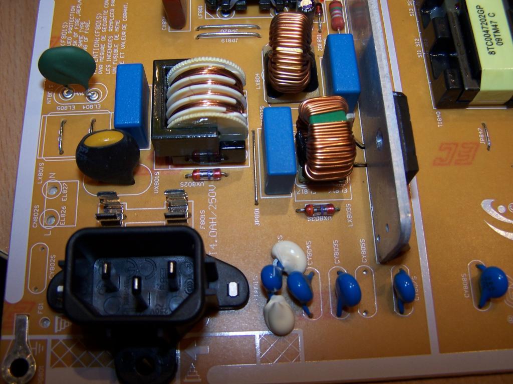
    Last edited by tw2005; 21-07-17 at 07:46 AM.

  • The Following User Says Thank You to tw2005 For This Useful Post:

    loopyloo (26-07-17)

  • #59
    Senior Member
    loopyloo's Avatar
    Join Date
    Feb 2008
    Location
    Mid North Coast NSW . Australia
    Age
    67
    Posts
    2,208
    Thanks
    1,431
    Thanked 470 Times in 314 Posts
    Rep Power
    416
    Reputation
    7317

    Default

    Ha ha yep Samsung. You done well.
    Spark gap is what I figured too. Should be SG803S lol.

  • #60
    Senior Member
    loopyloo's Avatar
    Join Date
    Feb 2008
    Location
    Mid North Coast NSW . Australia
    Age
    67
    Posts
    2,208
    Thanks
    1,431
    Thanked 470 Times in 314 Posts
    Rep Power
    416
    Reputation
    7317

    Default

    Now back to the LG.
    I've got 340v across that C610. Also got 340v on the drain of Q601, Q602, Q101 but nothing on Q102. What do you reckon ? IC101 gone ?

  • Page 3 of 16 FirstFirst 12345678910111213 ... LastLast

    Bookmarks

    Posting Permissions

    • You may not post new threads
    • You may not post replies
    • You may not post attachments
    • You may not edit your posts
    •