


 Reply With Quote
No secrets here.
It's not just the electro caps in the power supply that cause grief, they deteriorate on the main board as well.
Another possibility is the LNB and/or connections... especially if all decoders are exhibiting the same issue.


Hi all,
Just wondering if there has been any update as to the glitching problem. Yes the decoder has a replacement PSU & yes the PER (BER) does fluctuate. Mostly when warm. Anyone found a fix for this problem yet? If I only had one with this problem it would be in the bin by now, however there are a few (all with the same symptom) just waiting on me to re-invent the wheel again.
Perhaps MTV has the problem sorted & is remaining silent. I have time for a quick look this week but can't spend too much time on an old decoder, better to replace it with 4123PVR & get factory warranty.
Thanks in advance.
| Look Here -> |


No secrets here.
It's not just the electro caps in the power supply that cause grief, they deteriorate on the main board as well.
Another possibility is the LNB and/or connections... especially if all decoders are exhibiting the same issue.
Thanks MTV, got it sorted. two 100uf 16v electros in the tuner circuit & two VERY fiddly SMD electros. I managed to break one pad off but also got a fix on it. They will be fiddly to fix unless you have good eyesight, a steady hand & fine tipped iron. I completed 2 boxes so far & they are under test for the next day or two just to be sure that is the fault. I might concider just piggybacking some pcb electros over the smd caps for convenience. Just for anyone else looking; remove the main PCB for ease of access to the components. Hope this helps. PS: did not take any pics of this repair but will try & post some later for others to see. My work is plenty shabby but all looks good when the cover is replaced. (lol)
Some pics would be great.
How did you determine that these caps were the culprits?
Mostly helpful member
A tad of reverse engineering , visual observation & HEAPS of luck. I will be on the job repairing some more over the weekend so will post some pics. A picture is worth a thousand words. Also am going to try a piggyback with the 3 SMD electros. Just from looking at the circuit I might try some 220uf 25V PCB mount ones as there is plenty of room. All my butchers evils will be hidden once the lid goes on the box (lol)
Almost forgot the 2 boxes on test have not failed so far. They are both in a cardboard box sealed up to generate heat, I'm fairly confident the problem is now solved.
Yes heat appears to be the catalyst.Originally Posted by Softek2

Well done.
Mostly helpful member
the completed work.
Just an update. All decoders working fine after 4 days in the "hot box". I also believe it is the 2 pesky SMD caps that are the problem & not the other 2 PCB mount caps. I do agree that heat is a factor but at least 2 out of the bunch (so far) were not heat conscious. For the PM earlier - check the top right hand corner of the PCB.
Thanks for the image and info, I have several boxes with the glitching problem which I will attempt to repair.
I see on the image 2 black pcb caps, are these 16v 100uF like the original or 16v 220uF?
Did you also replace the 16v 220uF SMD which is partially hidden?
I will need to practice my fine soldering skills on some old computer boards before I wreck the Vast boxes.
Which SMD removal method did you use? I don't have a small hot air gun yet.
The other methods available are de-solder with a small iron or twist off!
Regards, Phil
Many thanks - just fixed my box by replacing the three surface mount electros - great!
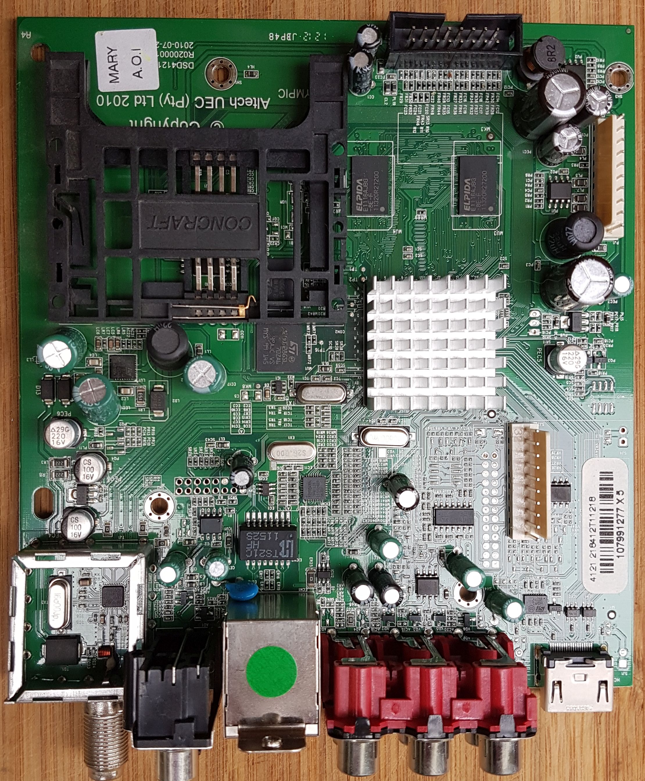
Here is a shot of the main board showing the offending SMDs.
See bottom left above the RF cage.
2 x 16v 100uf
1 x 16v 220uF
Hint: Remove the rear panel to free the main board
Mostly helpful member
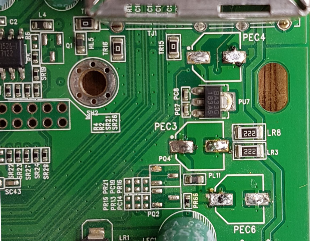
SMDs off.
PEC 3 - 100uF 16v
PEC 4 - 100uF 16v
PEC 6 - 220uF 16v
Last edited by Farmsky; 18-06-18 at 04:01 PM.
Mostly helpful member
Do you know the reason why these would be SMDs and not standard discrete caps?
I replaced the SMD caps as suggested and the box is all working fine now.
 Posting Permissions


Bookmarks