


 Reply With Quote
GT250 (13-02-19),hinekadon (12-02-19),Skepticist (12-02-19)


+ on VDD as Skepticist said !Originally Posted by GT250

I don't see that resistor !
For the quick test you can use a 1W or make up out of 4X 0.25 watt resistors you have lying around. Doesn't have to be exactly 22Ω, just roughly.
You just want to see if there is still 3-5V between Vdd and Vss. If it is zero then it is toast if you ruled out the caps, 0.7-2V might be something pulling down an output.
It won't be functioning because it is missing the AC on it's input.
If you have a Frequency test range on your Multimeter you might be able check the clock. One test lead on Vss and the other on the resonator, try which side. I suspect 4Mhz.
I don't suppose you have a CRO or DSO?
Update: A deletion of features that work well and ain't broke but are deemed outdated in order to add things that are up to date and broken.
Compatibility: A word soon to be deleted from our dictionaries as it is outdated.
Humans: Entities that are not only outdated but broken... AI-self-learning-update-error...terminate...terminate...
GT250 (13-02-19),hinekadon (12-02-19),Skepticist (12-02-19)
Doesn't matter for this - it just acts as a ballast to limit the current in case there's a fault like overload or short cct

Guys.
Sorry for lack of reply. Just got back in now.
I got called out for an oldies emergency, but all's well thank god
Ok. I do have a bunch of 4qty 22Ω 1/4W R's, so I guess they will do - so 22Ω @1W ?
Nomeat says: "You just want to see if there is still 3-5V between Vdd and Vss". So I assume that when I connect the 5VDC on Vdd and Vss, you want me to measure the connections that I'm supplying the 5VDC on?
I have a Proteck 6502 20Mhz (A Dick Smith I think), CRO - but don't go thereIt would require another post of a zillion pages for me to work it out.
I have a Fluke 289 if that helps for Freq reading..?
Tomorrow, pending oldies (they should be ok), I'll get stuck into it.
Look after your health. Money doesn't matter.
Those resistors in series/parallel will do fine - they'll get hot if there's a short circuit (on 5V) but will be ok for a short time.
If the PIC takes 20mA there will only be about 400mV drop across the resistor so the Vdd-Vss voltage will be around 4.6V in that case
Yes voltage is across Vdd/Vss and needs to be 3V or higher up to 5.5V max
The frequency on the resonator is likely to be in the range 4 to 20 MHz if your Fluke can pick that up, any numbers on the resonator?
Last edited by Skepticist; 12-02-19 at 08:10 PM.
No it won't
Only good for up to 1Mhz, maybe it shows OVL or just some random numbers but if it shows 0Hz then you will know nothing. The CRO would be the shot, jump in the cold water.
If anything this thread achieves, it's that you learnt something even if you can't fix it but you might then have figured out your CRO ...priceless!
Edit: This one? Come on... my TV remote looks harder to use then that
OK quick run through before this goes back and forth for days.
- Power on
- Wait for a line or dot(toggle off the XY button) to appear. You might have to move the position knobs and set the line in the centre and then set Intensity to a comfortable brightness and Focus so the line is thin and sharp.
- Make sure none of the buttons are depressed, just press CH1. Adjust to centre if required.
- Set VOLTS/DIV to 0.5V and the slider switch next to it to AC
- Set TRIG.MODE to Auto and SOURCE to INT
- Set for now TIME/DIV to 10ms
- Plug in your probe in CH1 input and just touch it's tip without touching anything else
- If you see some really messed up looking 50Hz wave then the CRO is good to go.
- You can now set TIME/DIV to 1ms and VOLTS/DIV to 2V
- Check if the probe has a 10X setting, if yes set it to that and change VOLTS/DIV to 0.2V
- Place the probe on that little bit of metal under CAL 5V. You should see a square wave which looks like two horizontal dotted lines. If it is just two continuos lines turn TIME/DIV clockwise until you see the dotted lines or a square wave with also vertical lines.
- Fire up your PIC with the 5V supply and place the probe's ground clip on Vss. I hope it still has a wire with the ground clip(they do break off eventually) otherwise find a way to connect the CRO's separate ground socket (with the Earth symbol) to Vss.
- Turn TIME/DIV to 1�s, maybe reduce VOLTS/DIV by one or two steps place the probe on the resonator and pray or hope that you see some sort of signal other than a straight horizontal line.
- By turning TIME/DIV and VOLTS/DIV you might be able to "tune" into a sine-like wave. It is not sine but your CRO can't display the actual waveform, don't worry about that.
I mentioned the probe setting 10x. This puts less load on the HF signal that the resonator generates. The 1X setting might disable the oscillation in a worst case scenario. I am not sure about the impedance of these resonators.
If you don't have a 10X probe and see no signal, remove the 5V and reconnect and then try the probe on the other side of the resonator than the first side you tried.
Last edited by Uncle Fester; 12-02-19 at 10:29 PM.
Update: A deletion of features that work well and ain't broke but are deemed outdated in order to add things that are up to date and broken.
Compatibility: A word soon to be deleted from our dictionaries as it is outdated.
Humans: Entities that are not only outdated but broken... AI-self-learning-update-error...terminate...terminate...
GT250 (13-02-19),hinekadon (12-02-19),Skepticist (12-02-19)

hi gt250 Im sure you are a little chicken of the scope but just think of it the same as when you first got your multi meter same thing !! you were shit scared of that werent you and afraid you would blow the guts out of it then but now your ok with it and can use it quite competently to give us readings on you posts, your scope is no different same two leads and we are only playing with current limited 5v dc . So lets see a bit of that hairy chest and some guts ok regards don
ok lets see the first thing is to power it up
2nd put a probe on it on ch1
take the probe end and hook it to the pin that says cal , you will see a trace show up on the screen
have a fiddle with the vert knob and see how that works
the have a play with the timebase or hoz control and see how that changes things
thats all there is to using a scope now you can hook it up to any thing "within reason "and adjust the knobs untill you can make sense of the readings where they are pointing
volts is vertical and time is hoz in milliseconds the screen is divided into divisions to make it easier to guess the levels! so way you go no problems !!!
Last edited by hinekadon; 12-02-19 at 09:52 PM. Reason: more
Uncle Fester (13-02-19)
Don't attempt to use the CRO on a live (mains AC) circuit unless you're using an isolating transformer as well otherwise the CRO will join the casualty list. That especially applies to this circuit that's 'floating' at mains potential when it's plugged in so connecting a probe's GND lead will create a nasty earth fault (flash, smoke, eye damage etc).
No problem at all if an external LV supply is used to power the electronics though - just don't attach the mixer to the mains.
First test is to see if the PIC supply voltage holds up with the 5V external supply via the 22ohm resistor. If the voltage is below 3V then there's no point in using the CRO.
Last edited by Skepticist; 12-02-19 at 10:40 PM.
hinekadon (13-02-19),Uncle Fester (13-02-19)
First many thanks to nomeat for the guide. The CRO is set. The 5VDC has a 22 Ω 1W in place.
I'm assuming the 'Resonator' is the CLK pins 16 or 15?
Here's a pic of nothing connected.
Probe on CLKIN Pin 16.
Probe on CLKOUT Pin 15.

Hi
Try altering the Time/Div knob, set it to a smaller value U/S/Div. If 10Khz one cycle is 100us, so you need it set to 50u/s or faster. Cannot read your current setting.
Skepticist (13-02-19)
Can't make out the CRO settings from the pictures IE volts/div and time/div but there does appear to be a stable high frequency signal there which is promising although it could be noise from your power supply. What was the voltage across Vdd-Vss while doing this test or even just the voltage drop across the 22 ohm resistor?
hinekadon (13-02-19)
Have been watching this thread.
Keep going guys, very interesting.

Looks like the settings are 10mv / 1us.
Skepticist (13-02-19)
Knocked up this schematic of the PIC board and can't see all the component values from the posted pictures so don't take it as gospel
Makes sense to me though
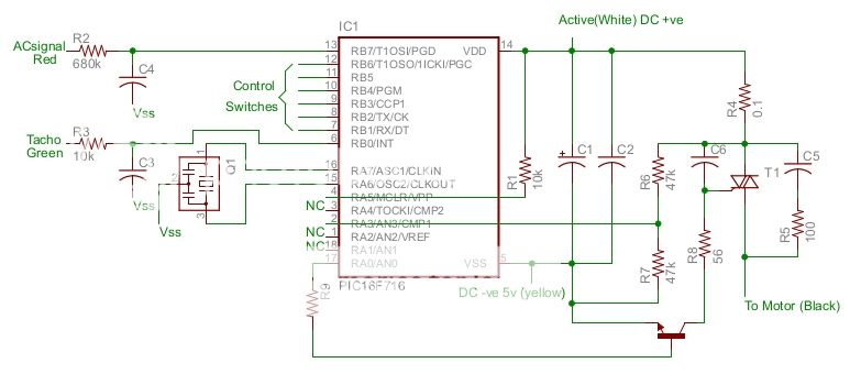
hinekadon (13-02-19),Uncle Fester (13-02-19),VroomVroom (26-02-19)
now heres a thought has the two white wires been put on the wrong terminals "cn204/cn201 " ?????
CN204 (neutral) is marked 'MO' which I take to mean 'motor' so the connections look correct to me. CN201 is the active going to the triac and the heavy black wire from the other side of the triac must be connected to the other motor terminal so it all adds up especially when considering the motor ran when the triac was bridged out earlier.

If you are too scared of the CRO, send it to me....... Seriously, This is getting interesting and, despite not having needed to play with anything remotely resembling electronics for decades (literally) I'm finding it interesting.
I'm out of my mind, but feel free to leave a message...
this is what a technical forum is all about!!!! makes me feel no so useless and gives experience to others as theres not enough brains used in this world now , just pissing around with programming radios is not electronics picking up a soldering iron make life active lol
thanks skeptic just having a overall look made me ask and does it matter where the active is on a triac i think not just not the gate but the transister going to the neg must be the fireing discharge of the other cap in the circuit????
Looks like an RC timer on the gate and the transistor starts the capacitor discharging gently via the series resistor. Considering the R & C values used, the timer period is very short and I see it performing a function somewhat like a diac in this application (a diac wouldn't trigger until the instantaneous sinewave voltage got to about 28V above 0).
The whole circuit is a bit unconventional but very flexible considering software determines whether it's a leading or trailing edge phase controller and it varies the power to maintain the selected speed for variable loads.
yep i concur , must be the r/c timer /etc acting as the diac looks like theres a few followers to the post , good
Ok. EDIT BELOW::: PIC setup.
I might have not got the settings correct on the CRO as nomeat had laid out. But I have now double checked and have it right - I hope.
With the voltage: From the PS it was 5.11VDC and across VSS Pin 5 and VDD Pin 14 it was 5.10VDC - so I'm assuming that's bad as there's no 'real' voltage drop?
First pic is the start with the probe on the CAL. If I turned the Time/DIV to the right a bit, I could actually see the Vertical lines, just! So good square wave!
Second pic is CLK-OUT Pin 14.
Third pic is CLK-IN Pin 15.
Fourth pic is VSS Pin 5.
The PIC setup for testing.

Last edited by GT250; 13-02-19 at 05:05 PM.
Skepticist (13-02-19),Uncle Fester (13-02-19)
 Posting Permissions


Bookmarks