Results 1 to 10 of 10

Thread: Chinese Plasma Cutter

  1. #1
    Member tytower's Avatar
    Join Date
    Jan 2008
    Posts
    352
    Thanks
    12
    Thanked 17 Times in 15 Posts
    Rep Power
    214
    Reputation
    238

    Default Chinese Plasma Cutter

    I have a Chinese CUT 50 brand plasma cutter.

    When I pull the trigger a relay clicks a buzzer sounds and an LED for overheating comes on so no go plasma cutter. The machine is completely cold.

    I'm guessing a temp sensor is broke and so turns the thing off.

    Where would the temp sensor or sensors be placed ? How can I find and test them?
    Last edited by tytower; 12-03-22 at 12:20 PM.
    My Health , my Family and my Property are not Government business. Governments should do what they were designed to do . Govern the issues that are best done by a central body in the country to protect it from foreign invasion.State Governments and Local Councils should be abolished to stop the duplication and waste of funds.

    To defeat corruption in the public service , give them three times the penalty. Have them agree on hiring.


Look Here ->
  • #2
    Premium Member
    wotnot's Avatar
    Join Date
    Nov 2019
    Location
    Scenic Rim, SE Qld
    Posts
    3,271
    Thanks
    1,476
    Thanked 2,969 Times in 1,528 Posts
    Rep Power
    1368
    Reputation
    60249

    Default

    Quote Originally Posted by tytower View Post
    I have a Chinese CUT 50 brand plasma cutter.

    When I pull the trigger a relay clicks a buzzer sounds and an LED for overheating comes on so no go plasma cutter. The machine is completely cold.

    I'm guessing a temp sensor is broke and so turns the thing off.

    Where would the temp sensor or sensors be placed ? How can I find and test them?

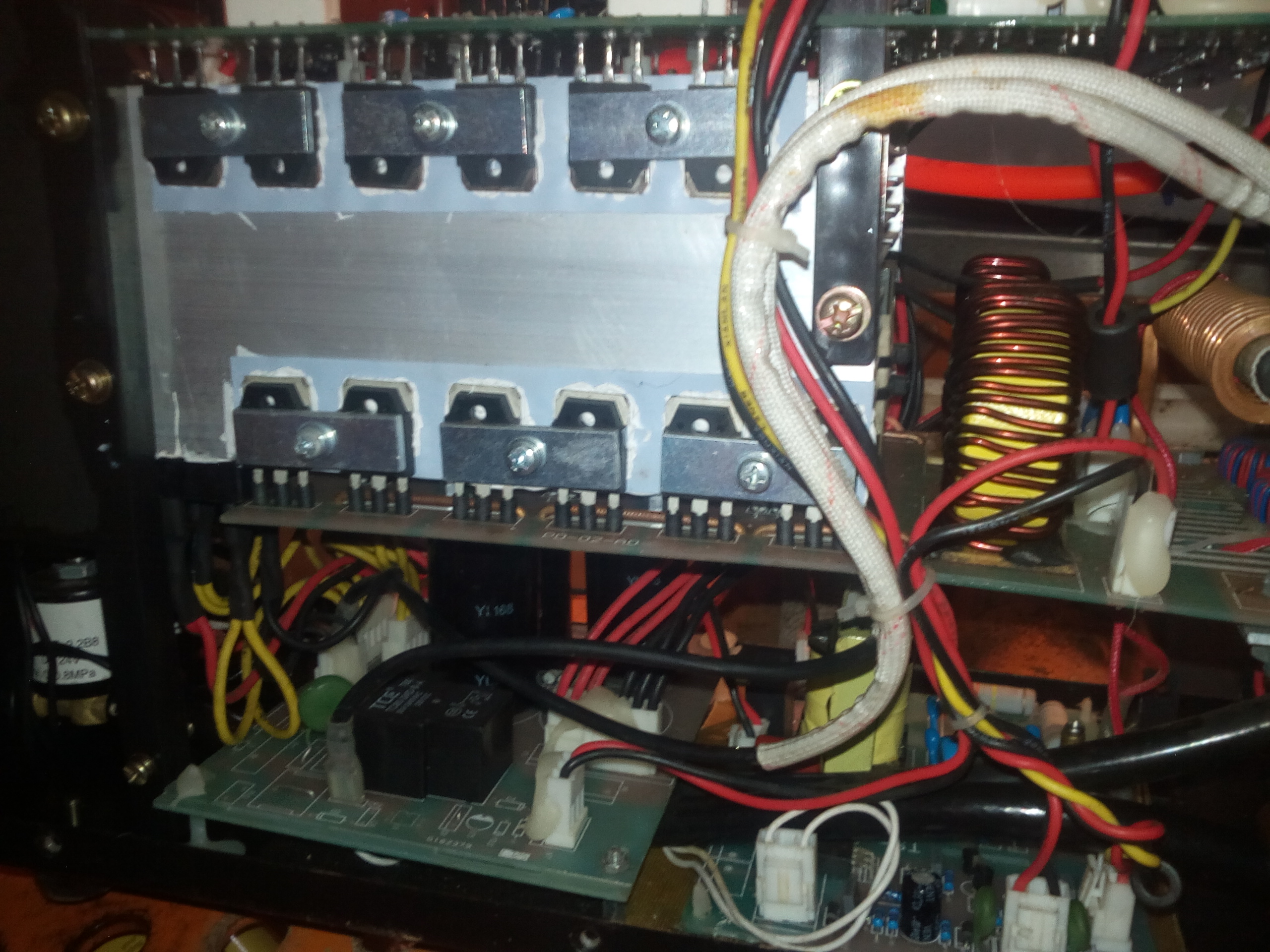
    Typically they mount a thermistor to the heatsink that carries the (fast) output diodes (some may have another thermistor mounted to the heatsink carrying the SMPS switchers)...but normally an overheat warning relates to the output section.

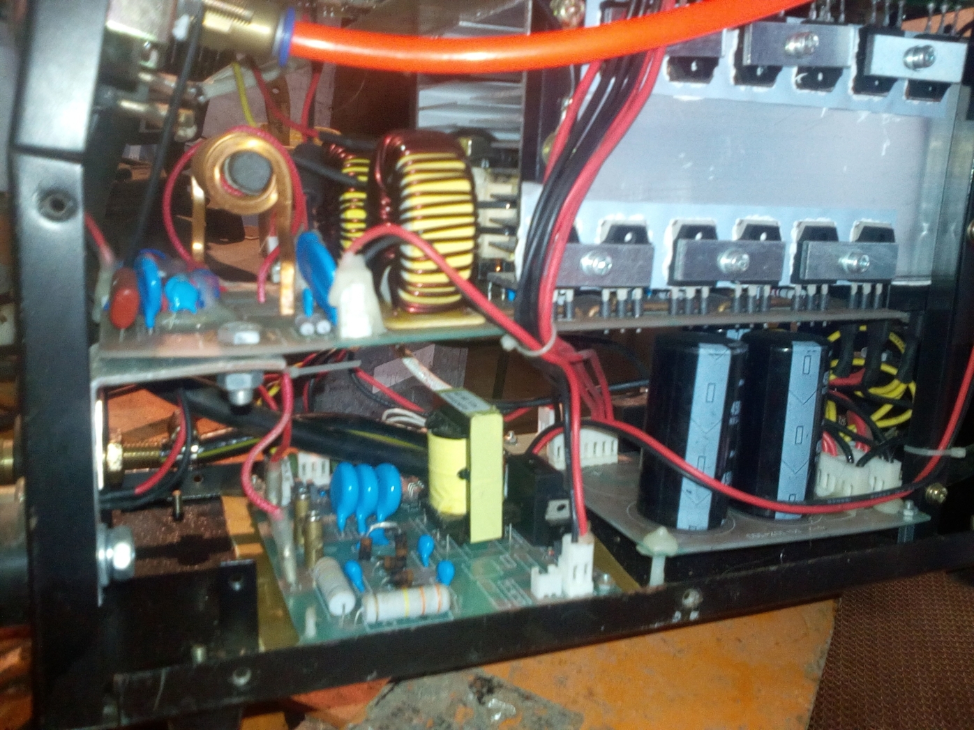
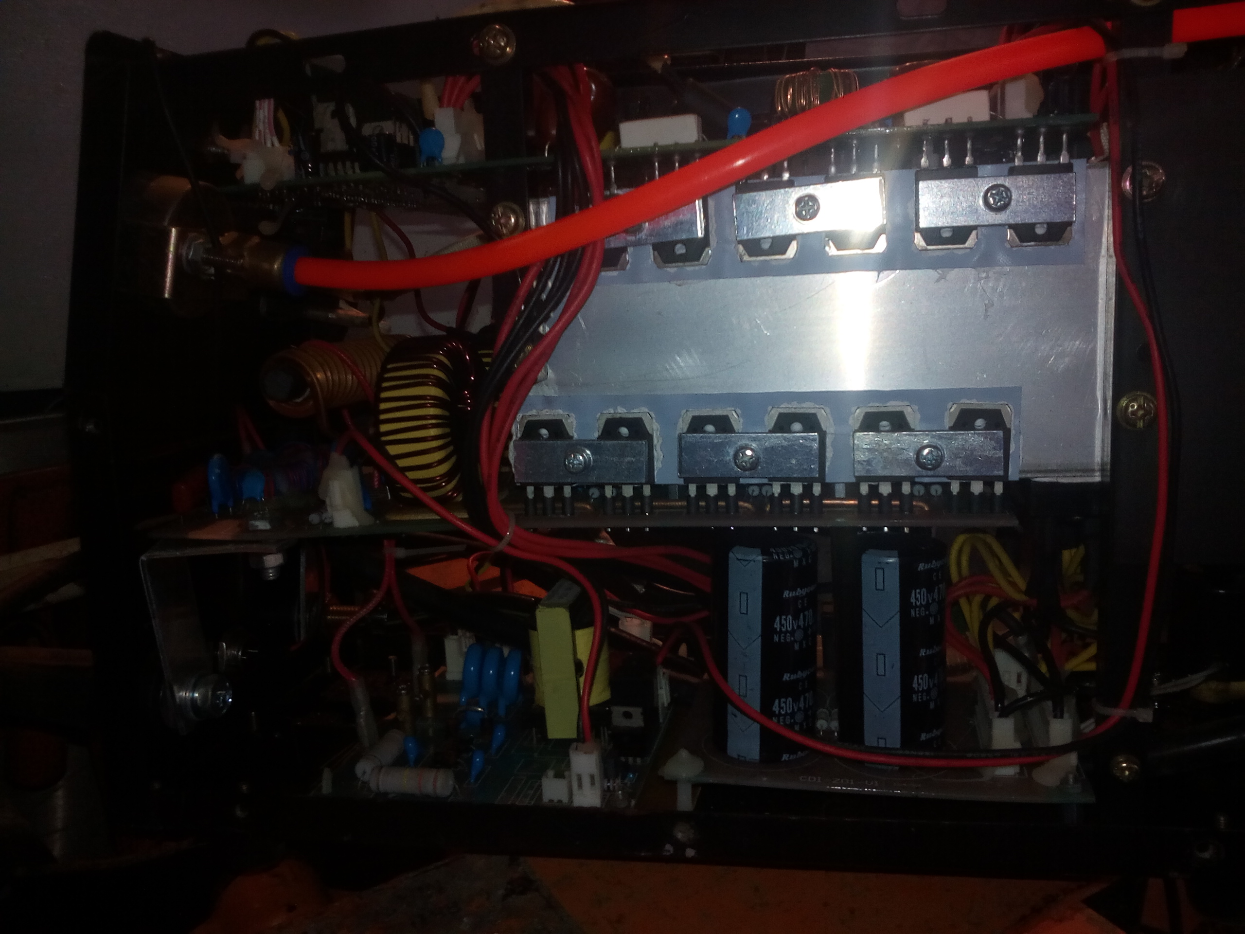
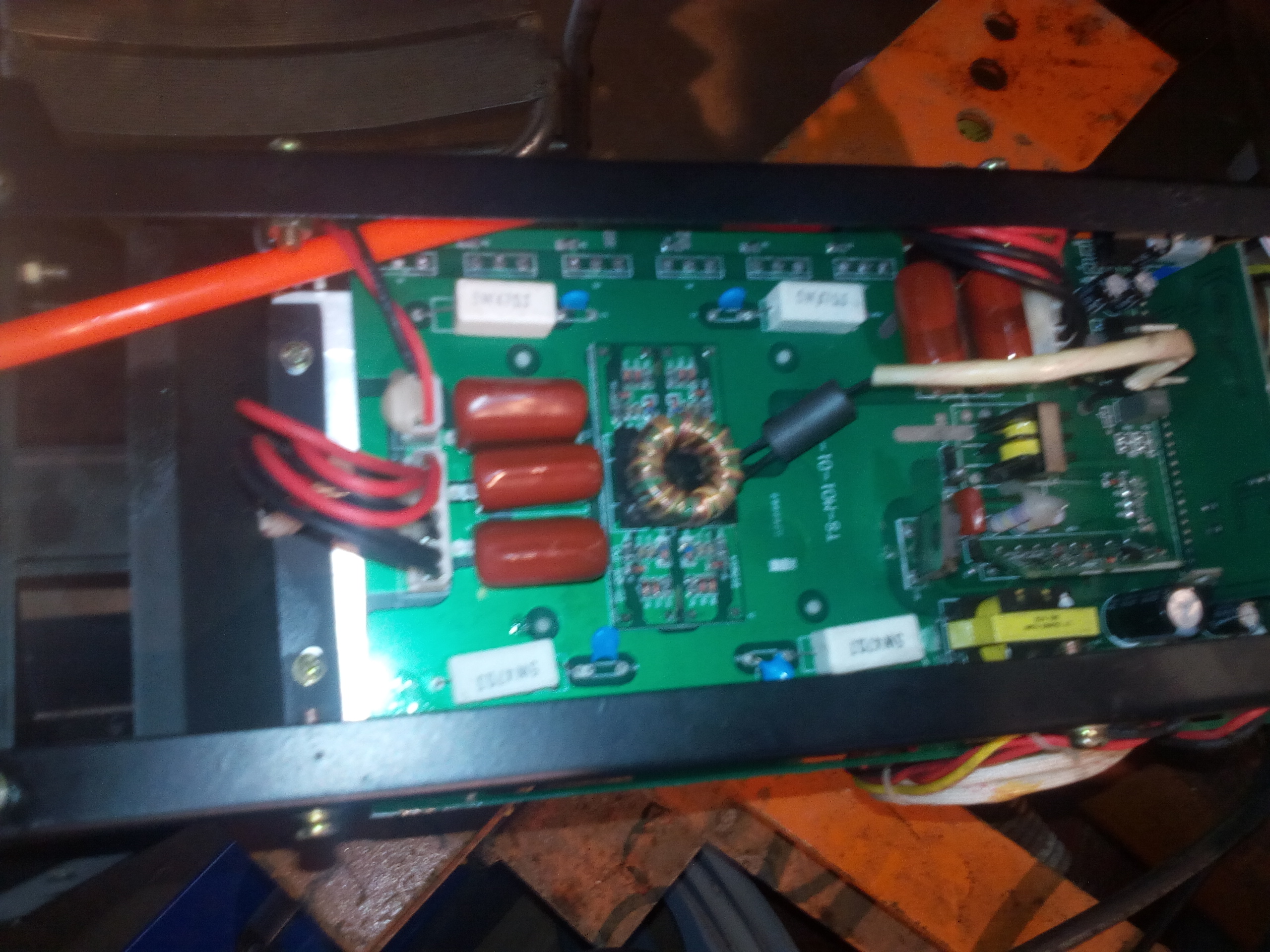
    On the Unimig plasma cut 40, they only have one mounted to the output section heatsink (the SMPS section is monitored/protected by current measurements on shunt resistors in the SMPS circuitry)

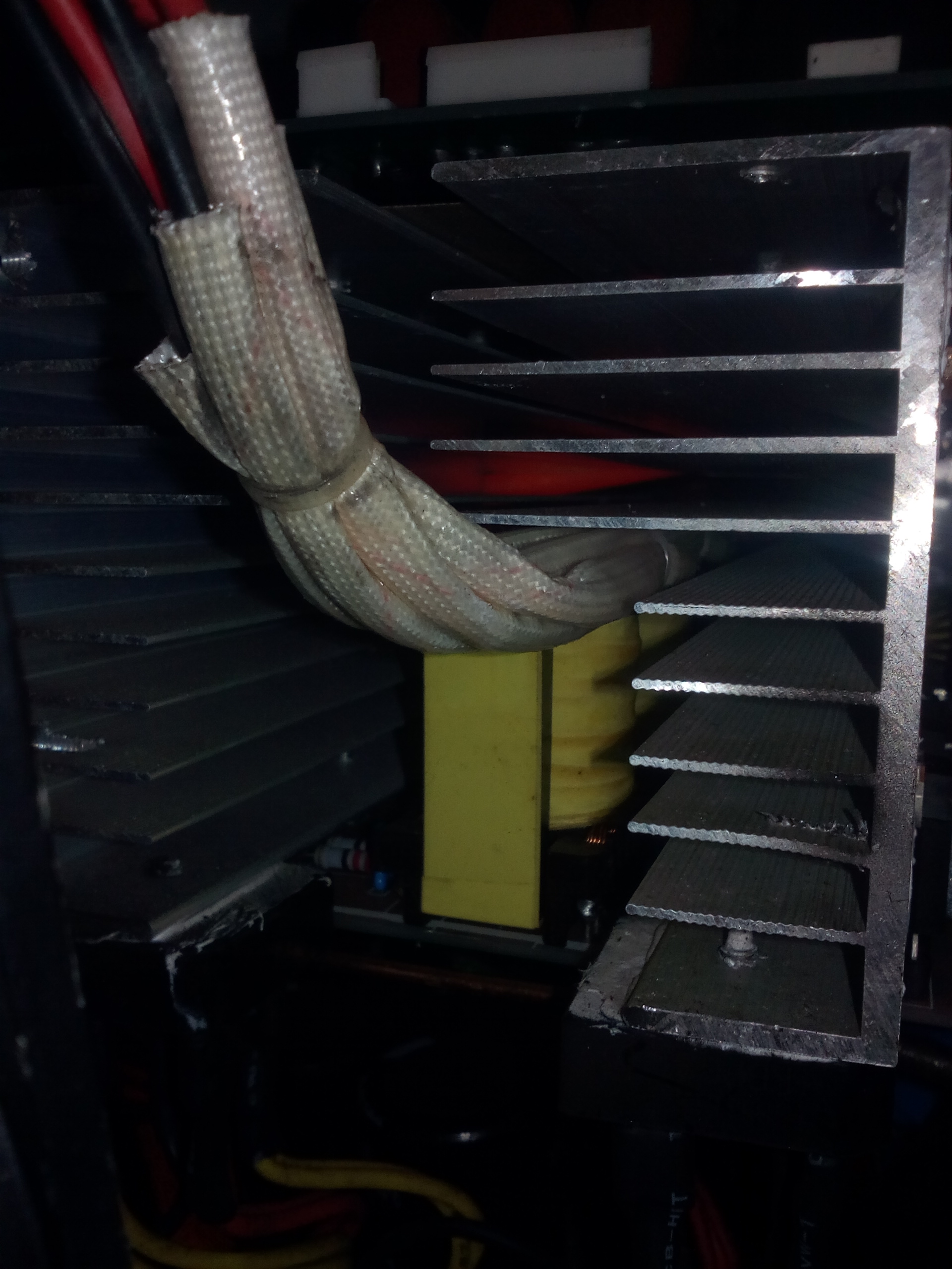
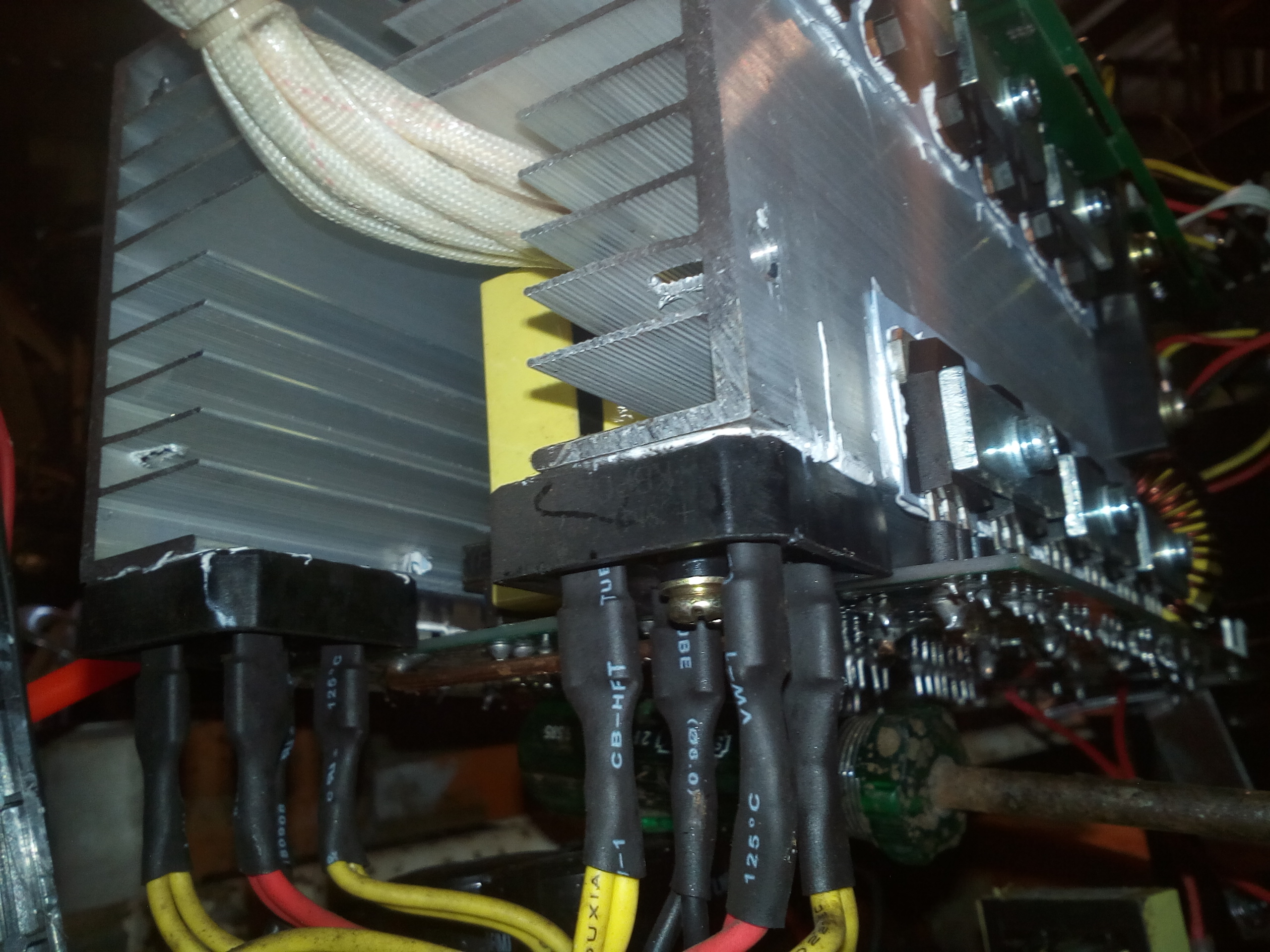
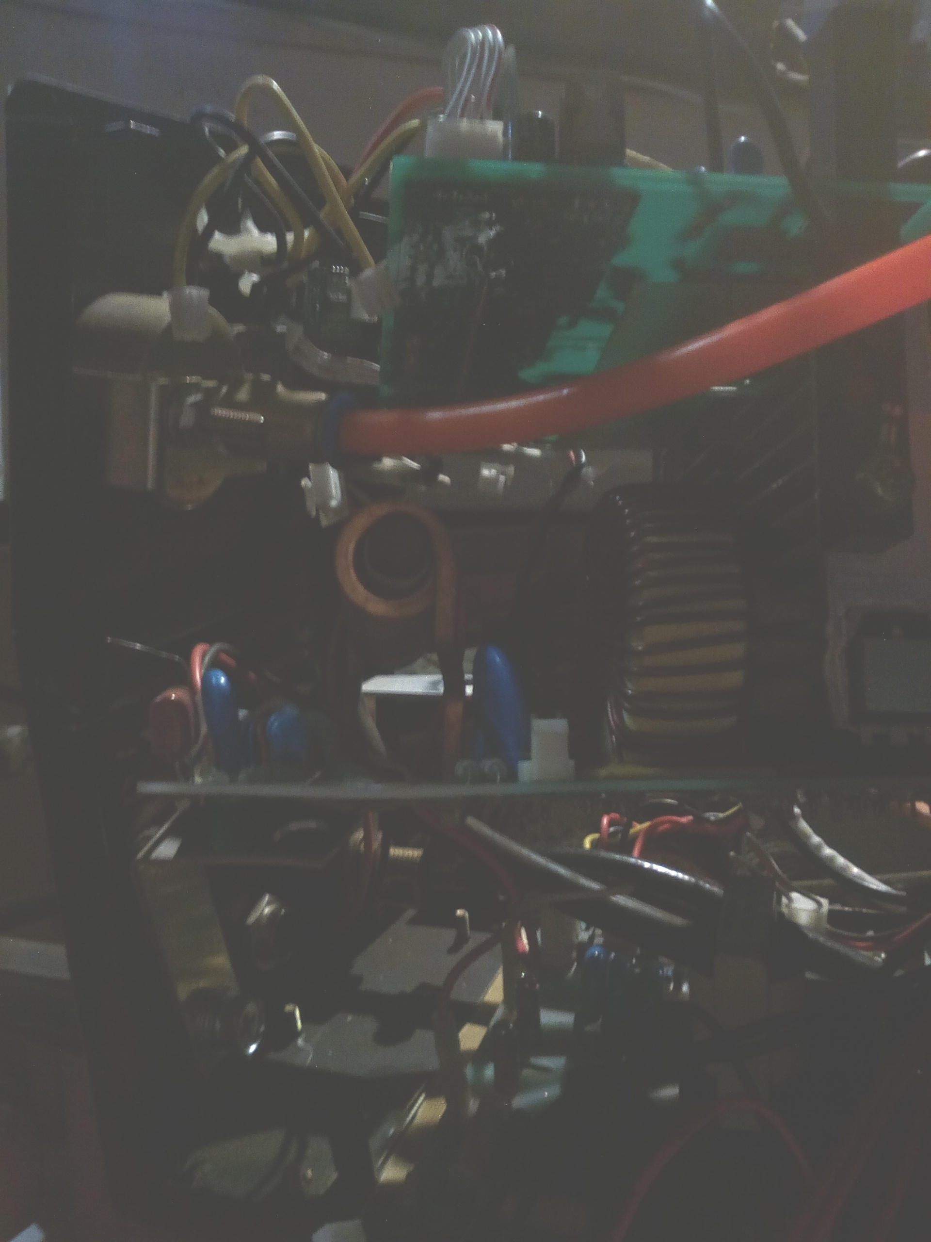
    Image of the thermistor on the output section heatsink on the Unimig....note; on these you have to do a near complete teardown and remove controller board to get at it)


    See ->

  • The Following 2 Users Say Thank You to wotnot For This Useful Post:

    tytower (12-03-22),VroomVroom (17-03-22)

  • #3
    Member tytower's Avatar
    Join Date
    Jan 2008
    Posts
    352
    Thanks
    12
    Thanked 17 Times in 15 Posts
    Rep Power
    214
    Reputation
    238

    Default

    Last edited by tytower; 16-03-22 at 08:38 PM.
    My Health , my Family and my Property are not Government business. Governments should do what they were designed to do . Govern the issues that are best done by a central body in the country to protect it from foreign invasion.State Governments and Local Councils should be abolished to stop the duplication and waste of funds.

    To defeat corruption in the public service , give them three times the penalty. Have them agree on hiring.

  • #4
    Premium Member
    wotnot's Avatar
    Join Date
    Nov 2019
    Location
    Scenic Rim, SE Qld
    Posts
    3,271
    Thanks
    1,476
    Thanked 2,969 Times in 1,528 Posts
    Rep Power
    1368
    Reputation
    60249

    Default

    I didn't see it in those images, but, where do this pair of white wires go? (out of the connector)


    edit: just thinking aloud, they could've cheated real horrorshow...(seen this with cheap chinese audio amps) -- instead of mounting a thermistor to the heatsink proper, I've seen them use little glass bead thermistor on the main PCB adjacent/under where the heatsink mounts to the PCB
    Last edited by wotnot; 16-03-22 at 10:16 PM.

  • #5
    Senior Member

    Join Date
    Jul 2010
    Posts
    2,235
    Thanks
    2,822
    Thanked 1,514 Times in 835 Posts
    Rep Power
    796
    Reputation
    27703

    Default

    is there significant warping on those PCBs ? doesnt look great

  • #6
    Member tytower's Avatar
    Join Date
    Jan 2008
    Posts
    352
    Thanks
    12
    Thanked 17 Times in 15 Posts
    Rep Power
    214
    Reputation
    238

    Default

    @VroomVroom

    No warping just they are not supported there as I was trying to get a look under and around each board so I have it pulled apart.
    My Health , my Family and my Property are not Government business. Governments should do what they were designed to do . Govern the issues that are best done by a central body in the country to protect it from foreign invasion.State Governments and Local Councils should be abolished to stop the duplication and waste of funds.

    To defeat corruption in the public service , give them three times the penalty. Have them agree on hiring.

  • #7
    Member tytower's Avatar
    Join Date
    Jan 2008
    Posts
    352
    Thanks
    12
    Thanked 17 Times in 15 Posts
    Rep Power
    214
    Reputation
    238

    Default

    @wotnot

    17 years ago I built me a lab power supply from a Silicon Chip Magazine design and kit. The temp sensing was done with transistors. As it got hotter the tranny switched more current and a comparator circuit flipped when it was too hot.

    So I'm looking for that possibility too.
    My Health , my Family and my Property are not Government business. Governments should do what they were designed to do . Govern the issues that are best done by a central body in the country to protect it from foreign invasion.State Governments and Local Councils should be abolished to stop the duplication and waste of funds.

    To defeat corruption in the public service , give them three times the penalty. Have them agree on hiring.

  • #8
    Premium Member
    wotnot's Avatar
    Join Date
    Nov 2019
    Location
    Scenic Rim, SE Qld
    Posts
    3,271
    Thanks
    1,476
    Thanked 2,969 Times in 1,528 Posts
    Rep Power
    1368
    Reputation
    60249

    Default

    Images are useful though - this all looks very familiar -->>

    The temp sensing was done with transistors.
    Yeah, but the chinese way is as cheap as possible -- transistor junctions cost heaps more than thermistors =)

  • The Following User Says Thank You to wotnot For This Useful Post:

    tytower (18-03-22)

  • #9
    Member tytower's Avatar
    Join Date
    Jan 2008
    Posts
    352
    Thanks
    12
    Thanked 17 Times in 15 Posts
    Rep Power
    214
    Reputation
    238

    Default

    Man thats a good reference . If I don't get it from there then I am simple. Thanks heaps .

    A little story . Bought an Audi A4 about 2003 model. I would start it in the morn and go to the PO about 15 minutes at 100K park clear the box and come back to start it and it would not.
    It was flooding I reckoned . Wait 1/2 hour or more to cool down and it started again?
    Checked a bit but the flooding gave it away . Fuel out the exhaust.
    It had 2 of those cheap sensors ,made in china ,in a holder that plugged into the motor. $ 85 AUD in Aus and about $250 to fit it .
    Ebay had them for $28

    What was happening was the one sensor worked and fed the instrument panel. The second didn't, so the car had some sort of default setting on that sensor and the cpu decided it was bloody cold so it set the choke for -20C . In Aus my ambient is about 25C up to 40C Motor was probably 120C . So Flooding. Must admit replacing it in the engine was a bugger of a job though.
    Last edited by tytower; 18-03-22 at 04:36 AM.
    My Health , my Family and my Property are not Government business. Governments should do what they were designed to do . Govern the issues that are best done by a central body in the country to protect it from foreign invasion.State Governments and Local Councils should be abolished to stop the duplication and waste of funds.

    To defeat corruption in the public service , give them three times the penalty. Have them agree on hiring.

  • #10
    Premium Member
    wotnot's Avatar
    Join Date
    Nov 2019
    Location
    Scenic Rim, SE Qld
    Posts
    3,271
    Thanks
    1,476
    Thanked 2,969 Times in 1,528 Posts
    Rep Power
    1368
    Reputation
    60249

    Default

    Quote Originally Posted by tytower View Post
    A little story . Bought an Audi A4 about 2003 model. I would start it in the morn and go to the PO about 15 minutes at 100K park clear the box and come back to start it and it would not.
    It was flooding I reckoned . Wait 1/2 hour or more to cool down and it started again?
    Checked a bit but the flooding gave it away . Fuel out the exhaust.
    It had 2 of those cheap sensors ,made in china ,in a holder that plugged into the motor. $ 85 AUD in Aus and about $250 to fit it .
    Ebay had them for $28

    What was happening was the one sensor worked and fed the instrument panel. The second didn't, so the car had some sort of default setting on that sensor and the cpu decided it was bloody cold so it set the choke for -20C . In Aus my ambient is about 25C up to 40C Motor was probably 120C . So Flooding. Must admit replacing it in the engine was a bugger of a job though.
    By the time I'd read the bit in bold, I knew to check CTS (coolant temp sensor) ; they used to run two sensors...the CTS on a 5volt reference, and the dash temp gauge sender (usually a 10v reference via regulator in dash cluster) ; more modern cars just use CTS, and send a drive signal to the dash temp gauge. Modern EFI engines do not have a choke ; when cold they increase the injector pulse duration to make engine fuel mixture rich -- likewise, the don't have a throttle stop screw to adjust idle rpm. and idle air is controlled by IACV (idle air control control valve), and nor do they have a fast idle cam for when the engine is cold (some use a cold start air admittance valve, some use an auxiliary air control valve, and others an air regulator with a bimetallic strip that closes the regulator as the engine heats up)

    I've had a couple of coolant temp sensors fail over the years ; I carry a 3K9 .5watt resistor in the glovebox, so I can unplug the failed sensor and bridge the terminals with the resistor (3K9 makes the ECU think the engine is up to normal operating temp) -- normally they still start cold like this, because ECU has a reading on IAT (intake air temp), and usually provides some enrichment in response to that...but this trick is a handy workaround until one can source/fit a new sensor =)

  • The Following 3 Users Say Thank You to wotnot For This Useful Post:

    lsemmens (19-03-22),MrFixit (24-04-22),Softek2 (18-03-22)

  • Bookmarks

    Posting Permissions

    • You may not post new threads
    • You may not post replies
    • You may not post attachments
    • You may not edit your posts
    •