Page 3 of 3 FirstFirst 123
Results 41 to 57 of 57

Thread: Jaycar MKII problems

  1. #41
    Senior Member
    best4less's Avatar
    Join Date
    Jan 2008
    Location
    Australia
    Posts
    7,684
    Thanks
    3,487
    Thanked 2,207 Times in 1,132 Posts
    Rep Power
    758
    Reputation
    15165

    Default

    Swap IC2 and IC3 over and see if you are getting the 2.55 volts on IC2 and the 4.98volts on IC1 pin2 ????
    and use your finger to see if the chip is getting hot (don't burn your finger LOL)
    When you do things right, people won't be sure that you have done anything at all


  • #42
    Senior Member
    freakee1's Avatar
    Join Date
    Jan 2008
    Location
    somewhere warmer
    Posts
    1,442
    Thanks
    227
    Thanked 770 Times in 406 Posts
    Rep Power
    432
    Reputation
    9254

    Default

    Quote Originally Posted by gw1 View Post
    Using Jaycar reader, if you're able to read card details (eg provider id and HSN) then almost certainly there's nothing wrong with your hardware. If there was a fault then it wouldn't get that far.

    The fact that the ATR is intelligible tells you that the RxD section is working and there's nothing wrong with your crystal or software baud setting. The fact that additional card details (provider id etc) were received tells you that commands get through to the card ok, ie the TxD section is working.

    So if you're reading card details but unable to update keys etc then it's purely a software problem. For example wafers running AusGold can only be reprogrammed using one specific program, intentionally so to combat wafer cloning (back in the days when sellers sold silver wafers for pay tv). It was a bit before my time but that's my understanding of AusGold.

    As I remember it, ^lave's LMEdit was an alternative to ggedit. They were designed for Ghost Ghold / Ghost Silver / Ghost Fun / Ghost Emerald. They aren't compatible with AusGold, which besides having scrambled commands used a completely different memory map. When updating wafers you need to start by identifying your code and then using the appropriate updater application. The wrong updater application will never work, no matter what hardware or Windows version you use.

    Updaters like FMEdit and LMEdit work by repeatedly calling a 'raw write' command that programs a data string to a specified address in EEPROM (internal or external). The addresses it uses for each piece of data need to be correct otherwise at best your update will be unsuccessful; you could just as easily overwrite some other important data in EEPROM and effectively trash it. If that happens you'll be unable to revive your wafer even if you subsequently used the correct update tool: you'd need to completely reprogram it.

    Comments by others about using Win98 instead of XP or Vista are valid too. I've usually been able to get XP working but for device programming it can be handy to keep a Win98 partition around as some programs, especially older ones, really do work better with '98 than anything else.

    Also relevant is serial port. If trying to use a USB serial adapter and having problems the first thing to do is get rid of the USB adapter and run straight off the motherboard (or a PCI serial card). USB adapters can be OK in some applications but they're also notoriously problematic. Vista too is notorious for giving problems. If having trouble with device programming on Vista then the first thing to do is to try an XP machine instead.

    Anyway it sounds like your hardware is ok. good luck.
    Hillbilly - worth a read again.........

    I have had plenty of dealings with GW1 and I would say that this member knows more about the Jaycar Mk 2's that the guys that designed the board.........

    again - what software??????????


    f

  • #43
    Senior Member hillbilly's Avatar
    Join Date
    Nov 2008
    Posts
    696
    Thanks
    90
    Thanked 116 Times in 86 Posts
    Rep Power
    222
    Reputation
    569

    Default

    ok I've tinkered with it a bit more and I'm getting better results, but still not good! (I have no idea what I did to change the reading either)
    my reading are now
    IC2 between pin 7 & 14 = 2.55v
    IC3 between pin 7 & 14 = 4.88v
    IC1 pin 2 = 8.6v
    IC1 pin 6 = -7.68v
    D3 = 15.3v
    ZD1 = 12.8v

    I've tried LMedit ICprog and GGedit, all come up with the same error.

    I swapped the chips IC2 & IC3 over and they still read the same

    and yes pin 7 on IC3 was out when the pic was taken (whoops)

  • #44
    Senior Member
    intelliGEORGE's Avatar
    Join Date
    Jan 2008
    Location
    Sydney, AUSTRALIA
    Age
    43
    Posts
    4,106
    Thanks
    884
    Thanked 1,484 Times in 691 Posts
    Rep Power
    479
    Reputation
    7236

    Default

    Quote Originally Posted by hillbilly View Post
    Well I tested with the multimeter and got some irregular readings

    now this is what I get
    IC2 between pin 7 & 14 = 2.55v
    IC3 between pin 7 & 14 = 4.88v
    IC1 pin 2 = 4.98v
    IC1 pin 6 = -7.18v
    D3 = 15.3v
    ZD1 = 12.8v

    does anyone know were I should be looking?
    I'd be looking at REG1 (78L05), this voltage regulator produces an output voltage which is close to 5V (within the range 4.75V to 5.25V)

    First check that the input voltage is in the range 7.5V to 35V. Then make sure that the output voltage is +5V (at the regulator itself).

    If there is a fault, check that:

    The voltage regulator has been connected the right way round
    The voltage on the centre pin is 0V
    The voltage on the input voltage pin is correct

    If there is a fault, check the tracks and solder joints.

  • #45
    Senior Member hillbilly's Avatar
    Join Date
    Nov 2008
    Posts
    696
    Thanks
    90
    Thanked 116 Times in 86 Posts
    Rep Power
    222
    Reputation
    569

    Default

    Just checked that and all is good

    Input = 11.25v
    centre = 0v
    output = 4.98v

    I also got ICprog to work, I didn't have 16F877 selected, so that worked, but why no LMedit?

  • #46
    Senior Member
    freakee1's Avatar
    Join Date
    Jan 2008
    Location
    somewhere warmer
    Posts
    1,442
    Thanks
    227
    Thanked 770 Times in 406 Posts
    Rep Power
    432
    Reputation
    9254

    Default

    Quote Originally Posted by hillbilly View Post
    I've tried LMedit ICprog and GGedit, all come up with the same error.


    Have you tried these programmes with a goldie? - I'm not sure that they will work writing to a gam - never tried - not likely too, might have to ask decapper......or B4L?

    I would say that it is working fine - as others have said here - if it can get a legit ATR - then it is working - Streeter75 put up alot of software for a gam - might be worth having a look at post 5 of .........


    f

  • #47
    Senior Member hillbilly's Avatar
    Join Date
    Nov 2008
    Posts
    696
    Thanks
    90
    Thanked 116 Times in 86 Posts
    Rep Power
    222
    Reputation
    569

    Default

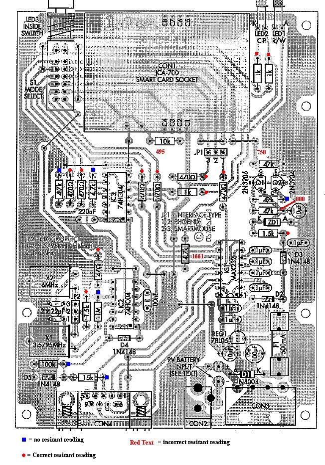
    I can't get FMcard to work either, I don't really understand why ICprog will read the card but nothing else will, I still think its a hardware problem, so I got the mutimeter out and tested the resistors, I'm a complete noob with this sort of stuff but it didn't make any sense to me

    Red circle = correct reading
    Blue squire = No reading at all
    Red Text = incorrect reading


  • #48
    Junior Member Gun Powder's Avatar
    Join Date
    Nov 2008
    Age
    48
    Posts
    13
    Thanks
    0
    Thanked 0 Times in 0 Posts
    Rep Power
    0
    Reputation
    10

    Talking

    Unfortunately, you can't really measure the impedance of resistors while they are "in-circuit", other resistors in parallel will change the measured value significantly, capacitors will charge up and give you a constantly changing reading etc..

    It sounds like the hardware is working properly, but there might be a few traps for you to check..

    • What kind of serial cable are you using, does it have lines for RTS/CTS etc, or is it just Rx/Tx/Gnd? If the cable is wrong, you will probably read back all 00's
    • Make sure you select "Open File" in ic-prog, not "Open Data File" (this tricked me at first)
    • Clear all checkboxes, (CP, etc) - WDT is watchdog timer, and will reset the card every 100mS or so unless the firmware is written to 'kick the dog', this should be off.


    I'd go down to Jaycar, and buy a standard, blank 16F84+24C16 (gold) card, and try programming that with the rb7 bootloader using by following the , Make sure you can then read & write to EEPROM, using your own text string with a proud message.

    Once you know the hardware works 100%, you then need to find out why the software is causing problems, make sure you have the latest LMedit etc.

    Use the smartcard wizard in ic-prog to program your bootloader, EEPROM, PIC code with the instructions in this . Starting with a Gold Card means you don't have to fuss about with a bootloader, one less thing to worry about.

    Then you should be able to read it into LMedit, and modify things to suit.

    Doing a Gold Card is almost easy, providing you follow the instructions thoroughly and slowly.

    Thanks to everyones files I've linked.. They are the best versions of everything I've found..

    If you mention where you live, maybe someone local can have a look at your kit, and check it. Maybe help you flash your first card too to get the hang of it?

  • #49
    Senior Member
    LeroyPatrol's Avatar
    Join Date
    Jan 2008
    Location
    N.E. Vic
    Posts
    16,229
    Thanks
    3,528
    Thanked 4,710 Times in 2,797 Posts
    Rep Power
    1670
    Reputation
    46551

    Default

    suggestions:

    Try another cable
    Try another com port
    Try another PC

    that low voltage reading on IC2 is a concern.

    Leroy

  • #50
    Senior Member gw1's Avatar
    Join Date
    Jan 2008
    Location
    Hobart
    Posts
    957
    Thanks
    49
    Thanked 608 Times in 213 Posts
    Rep Power
    268
    Reputation
    1901

    Default

    Almost certainly a dry solder joint problem. Get yourself a solder sucker, and preferably some better quality solder, and redo every joint that looks dull or where you can't clearly see nice shiny contact with both the component lead and the track.

    In particular redo the following joints which supply power to IC2. Nothing will work while you've only got half power. Double check that you're actually measuring the IC2 pins correctly - I find your reading hard to believe.


    If trouble persists PM me and I'll give you my postal address. It's probably quicker for me to fix it than figure it out by staring at photos

  • #51
    Senior Member z80's Avatar
    Join Date
    Jan 2008
    Posts
    5,840
    Thanks
    112
    Thanked 77 Times in 48 Posts
    Rep Power
    0
    Reputation
    708

    Default

    most people stuff up the two transistors, they are different....

  • #52
    Senior Member gw1's Avatar
    Join Date
    Jan 2008
    Location
    Hobart
    Posts
    957
    Thanks
    49
    Thanked 608 Times in 213 Posts
    Rep Power
    268
    Reputation
    1901

    Default

    Here's another quick run through of troubleshooting procedure.

    At each step the multimeter should be on DC range with black probe on a trusted GND point. Ordinarily I'd suggest the easiest place for GND is the wire link adjoining IC2 pin 7, but since the voltage on IC2 is suspect I recommend you use the anode of D5 (near the DB9 connector).

    Unplug serial cable and smartcard. Put JP2 on 6MHz, JP1 on Phoenix, push switch S1 *in*, and apply power.

    1) Check pin 14 of IC2 and IC3: both should be between 4.9 and 5.1 volts. If not then follow the solder joints, tracks and jumpers back to REG1. And check that the voltage on the input of REG1 (ie the fuse) is between 7.5 and 15 volts.

    2) Because you're having trouble with IC2, check that the voltage on IC2 pin 7 is 0V. Then, with no card inserted, and making sure you have JP2 in place (one way or the other), measure the voltage on the 47 ohm resistor (either leg will do). It should be between 2 and 3 volts - it's the average DC voltage of the square wave clock. If not then check the soldering of the crystals, the capacitors, the 1k5, the 1M, and all IC2 pins.

    3) Check IC1 pin 2 is between +8 and +10 volts, and IC1 pin 4 is between -7 and -10 volts. (If your meter is an old analog one then you'll need to swap red and black leads to measure the negative voltage). If voltages aren't right then check all solder joints on IC1 and surrounding capacitors.

    4) Check the voltage on the cathode of ZD1, it should be between 12.5 and 13.5 volts. If not then check orientation and solder joints of D2 and D3, the nearby 1uF capacitor and 1.5K resistor, the orientation of 10uF capacitor and Q1 & Q2, and joints underneath them all.

    5) With no card inserted and switch S1 *in* the green LED should be on and yellow & red off. Pin 7 of IC1 should be +9V (approx) if you've applied the inverter modification or -9V (approx) if you haven't. If you now insert a card the yellow LED should come on and pin 7 of IC1 should change to -9V with inverter modification or +9V without. If no yellow LED then check solder joints of smartcard socket, the orientation of the LEDs (both LED1 & LED2 should have their flat side facing the smartcard socket), and the solder joints on the nearby 1K restors. If pin 7 voltages aren't right then check S1 solder joints and those around IC1.

    6) with serial cable unplugged IC1 pin 14 should be approx -9V. if you now short IC2 pins 13 & 14 with a screwdriver the red LED should come on and IC1 pin 14 should swing up to +9V.

    good luck

  • #53
    Senior Member gw1's Avatar
    Join Date
    Jan 2008
    Location
    Hobart
    Posts
    957
    Thanks
    49
    Thanked 608 Times in 213 Posts
    Rep Power
    268
    Reputation
    1901

    Default

    A follow-up for those interested. The problem was the track to the GND input of the 78L05 regulator. Jaycar had drilled a hole right through the middle of the track, breaking it.


  • #54
    Senior Member z80's Avatar
    Join Date
    Jan 2008
    Posts
    5,840
    Thanks
    112
    Thanked 77 Times in 48 Posts
    Rep Power
    0
    Reputation
    708

    Default

    we should have seen that in post #50....nice work GW

  • #55
    Senior Member hillbilly's Avatar
    Join Date
    Nov 2008
    Posts
    696
    Thanks
    90
    Thanked 116 Times in 86 Posts
    Rep Power
    222
    Reputation
    569

    Default

    Thanks GW1, you will come well recommended by myself if anyone else requires your services.

  • #56
    Junior Member djst's Avatar
    Join Date
    Dec 2008
    Age
    53
    Posts
    30
    Thanks
    4
    Thanked 2 Times in 2 Posts
    Rep Power
    188
    Reputation
    20

    Default

    Reading this thread is almost like groundhog day,
    I brought a Jaycar mk2 yesterday,And had similar problems ,only to read this thread and check through my board to find the same problem.
    Thanks to all for the handy tips and advice.

  • #57
    Senior Member gw1's Avatar
    Join Date
    Jan 2008
    Location
    Hobart
    Posts
    957
    Thanks
    49
    Thanked 608 Times in 213 Posts
    Rep Power
    268
    Reputation
    1901

    Default

    There's more about the Jaycar MK II broken track problem in .

  • Page 3 of 3 FirstFirst 123

    Bookmarks

    Posting Permissions

    • You may not post new threads
    • You may not post replies
    • You may not post attachments
    • You may not edit your posts
    •