Results 1 to 13 of 13

Thread: Does it matter whether a shunt is on the Neg or Pos rail?

  1. #1
    Junior Member
    Join Date
    May 2008
    Posts
    146
    Thanks
    67
    Thanked 21 Times in 10 Posts
    Rep Power
    202
    Reputation
    153

    Default Does it matter whether a shunt is on the Neg or Pos rail?

    Hi Guys,

    I'm setting up a 12v accessory panel in the back of the Land Cruiser with various outlets, switches etc.

    I am also installing a combo meter to monitor volts, amps and charge from a solar panel (eventually).


    The wiring diagram for the meter below shows the shunt (100A) on the negative side of the load.


    Searching online shows various ways shunts are wired into circuits including the positive side of the load.

    Will it matter where I place the shunt in respect to the load?

    It will be easier to place the shunt on the positive side if at all possible as the negative is obviously the chassis/body.

    Appreciate any help you can provide.

    Thanks.


Look Here ->
  • #2
    Crazy Diamond
    Tiny's Avatar
    Join Date
    Dec 2010
    Location
    Tasmania
    Age
    64
    Posts
    6,393
    Thanks
    11,002
    Thanked 5,437 Times in 2,652 Posts
    Rep Power
    2157
    Reputation
    89077

    Default

    Will it matter where I place the shunt in respect to the load?
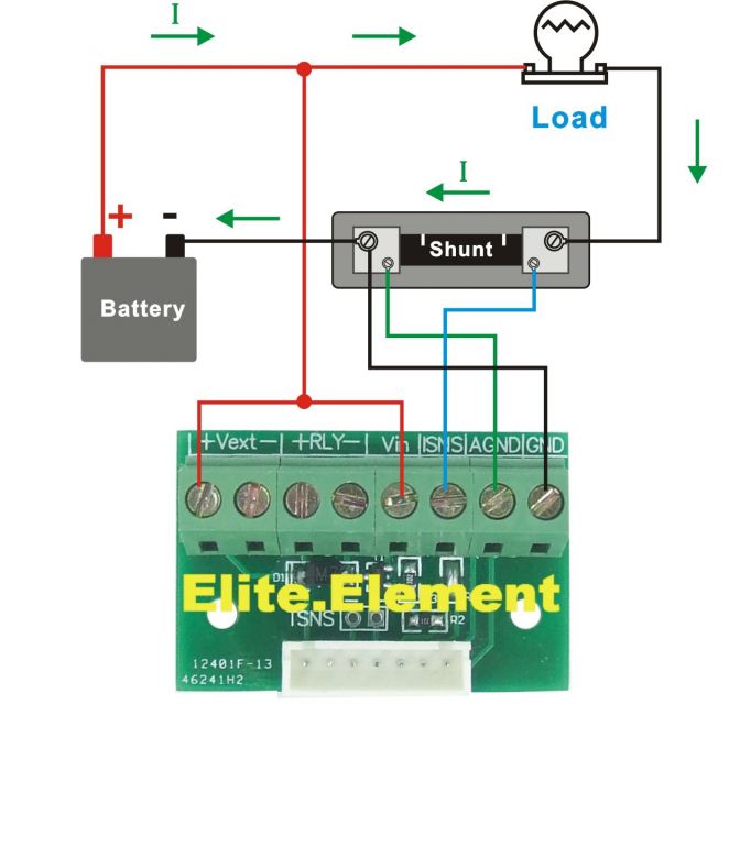
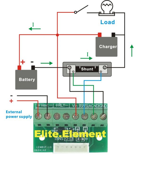
    IMO no not at all, the shunt is for the measure of the current flow. Pos or Neg, no difference except the sense wires are reversed depending on which you choose.
    In my house system with various Amp meters, shunts for calculations of input output etc, I have wired some on positive & some on negative as that is the most convenient position to reduce cable length.
    All work excellently as they should.

    Battery volts however is best measured at the battery or as close as possible. In the case of the vehicle you are not likely going to measure very far from the battery.

    Hope that helps.
    Cheers, Tiny
    "You can lead a person to knowledge, but you can't make them think? If you're not part of the solution, you're part of the problem.
    The information is out there; you just have to let it in."

  • The Following User Says Thank You to Tiny For This Useful Post:

    Krustyone (28-06-14)

  • #3
    Senior Member
    Reschs's Avatar
    Join Date
    Aug 2010
    Location
    Outside a few schooners
    Posts
    3,082
    Thanks
    914
    Thanked 2,151 Times in 1,060 Posts
    Rep Power
    936
    Reputation
    33318

    Default

    Because the metering circuit is powered by the supply that is being monitored, it is essential the shunt is in the negative.
    Otherwise tears.

  • The Following User Says Thank You to Reschs For This Useful Post:

    Krustyone (28-06-14)

  • #4
    Crazy Diamond
    Tiny's Avatar
    Join Date
    Dec 2010
    Location
    Tasmania
    Age
    64
    Posts
    6,393
    Thanks
    11,002
    Thanked 5,437 Times in 2,652 Posts
    Rep Power
    2157
    Reputation
    89077

    Default

    Quote Originally Posted by Reschs View Post
    Because the metering circuit is powered by the supply that is being monitored, it is essential the shunt is in the negative.
    Otherwise tears.
    As long as the power supply wiring is wired as positive & negative to circuit board the shunt can be on the positive side of the load.
    You just have to have the current flow sensing wires in the correct direction.
    Cheers, Tiny
    "You can lead a person to knowledge, but you can't make them think? If you're not part of the solution, you're part of the problem.
    The information is out there; you just have to let it in."

  • #5
    Crazy Diamond
    Tiny's Avatar
    Join Date
    Dec 2010
    Location
    Tasmania
    Age
    64
    Posts
    6,393
    Thanks
    11,002
    Thanked 5,437 Times in 2,652 Posts
    Rep Power
    2157
    Reputation
    89077

    Default

    Her is how I would wire it.
    Cheers, Tiny
    "You can lead a person to knowledge, but you can't make them think? If you're not part of the solution, you're part of the problem.
    The information is out there; you just have to let it in."

  • The Following User Says Thank You to Tiny For This Useful Post:

    Krustyone (28-06-14)

  • #6
    Junior Member
    Join Date
    May 2008
    Posts
    146
    Thanks
    67
    Thanked 21 Times in 10 Posts
    Rep Power
    202
    Reputation
    153

    Default

    Awesome.
    Thanks guys.

  • #7
    Junior Member
    Join Date
    May 2008
    Posts
    146
    Thanks
    67
    Thanked 21 Times in 10 Posts
    Rep Power
    202
    Reputation
    153

    Default

    Quote Originally Posted by Tiny View Post
    Her is how I would wire it.
    Appreciate the work on the diagram Tiny.!!!

  • #8
    Crazy Diamond
    Tiny's Avatar
    Join Date
    Dec 2010
    Location
    Tasmania
    Age
    64
    Posts
    6,393
    Thanks
    11,002
    Thanked 5,437 Times in 2,652 Posts
    Rep Power
    2157
    Reputation
    89077

    Default

    Quote Originally Posted by Krustyone View Post
    Awesome.
    Thanks guys.
    Just a warning with this; now with the shunt on the positive side all exposed connections are live & should be insulated or capped.
    The shunt being capable of 100A flow will of coarse need appropriate size wiring & connectors.
    A small plastic junction box over the whole shunt with a rubber or plastic mounting pad underneath wouldn't hurt either as the metal parts of it are positive & can be shorted to earth accidentally causing damage.
    All the above is why it is safer to wire the shunt on the negative rail, so although it can be done on the positive side the risk of grounding is high thru accidental contact or water earthing out the shunt.

    EDIT: BTW you do understand that you will void any warranty on this product by wiring it anyway other than their specifications.

    A good article in wiki below explains the limitations of both ways to measure current & the effects of common mode voltage.

    Last edited by Tiny; 28-06-14 at 03:23 PM.
    Cheers, Tiny
    "You can lead a person to knowledge, but you can't make them think? If you're not part of the solution, you're part of the problem.
    The information is out there; you just have to let it in."

  • The Following User Says Thank You to Tiny For This Useful Post:

    Krustyone (29-06-14)

  • #9
    Crazy Diamond
    Tiny's Avatar
    Join Date
    Dec 2010
    Location
    Tasmania
    Age
    64
    Posts
    6,393
    Thanks
    11,002
    Thanked 5,437 Times in 2,652 Posts
    Rep Power
    2157
    Reputation
    89077

    Default

    I got intrigued as to why there is a need for an external power supply so looked for your item & found another couple of wiring diags & some relevant info. See below.
    Appears it can have either external or internal power supply. The one you supplied in post #1 is for external power supply to the meter.

    All this leads to some questions & discussion; Are you intending to measure current to & from your under bonnet mounted battery from both the alternator & the solar panel? If so that changes a lot as this will be simpler to have the shunt placed under the bonnet on the negative rail.
    If you are only measuring current from the solar panel to an accessory battery in the back of the vehicle, then the shunt can be mounted there.
    If you are connecting another battery as an accessory battery; then if you connect it in parallel with the main battery you will need a VSR (voltage sensitive relay)

    I do like the look of the meter though & might look into them for my system.


    • It can measure Forward (Positive) and Reverse (Negative) current.
    • Combines many functions in one,
      Dual display for Voltage (V)
      Current (A), Power (W)
      Ampere-hour (Ah),
      Working Hours (H), Charging Time, Discharging Time
      Battery capacity (%)
    • Flexible On-line calibration function, calibrate Voltage and amps reading easily.
    • Adopting modular design, collocate indicator lights on the panel for various working status.
    • 4 digits LED for Voltage, Power, and Working hours reading, 3 digits LED for Current and Ah reading.
    • Lowe power consumption.
    • It does NOT require power when powered between 10-90V.
    • We can connect it by 2-wire(Power by Internal source), or 3-wire(Power by External source).


    Cheers, Tiny
    "You can lead a person to knowledge, but you can't make them think? If you're not part of the solution, you're part of the problem.
    The information is out there; you just have to let it in."

  • The Following User Says Thank You to Tiny For This Useful Post:

    Krustyone (29-06-14)

  • #10
    Senior Member
    Reschs's Avatar
    Join Date
    Aug 2010
    Location
    Outside a few schooners
    Posts
    3,082
    Thanks
    914
    Thanked 2,151 Times in 1,060 Posts
    Rep Power
    936
    Reputation
    33318

    Default

    Quote Originally Posted by Tiny View Post
    Her is how I would wire it.
    This has the Current Sense Ground connected to the Supply.
    Unless the metering power supply is fully floating with regard to the vehicle supply you are monitoring, you will let the smoke out.

  • The Following User Says Thank You to Reschs For This Useful Post:

    Krustyone (29-06-14)

  • #11
    Junior Member
    Join Date
    May 2008
    Posts
    146
    Thanks
    67
    Thanked 21 Times in 10 Posts
    Rep Power
    202
    Reputation
    153

    Default

    To both your points Reschs and Tiny, there is no need to utilise the external power source as per the original schematic.

    Ok. To open up on the project, I am running 2G cable from an auxiliary battery from under the bonnet, through a 200A circuit breaker (to protect for short circuits to ground) to the back of the vehicle to a box which will house various switches and accessories. (see below).


    The panel is designed to operate all circuits switched through automotive relays which in turn are channelled through the shunt to allow monitoring of the aux battery.
    The use of this panel will only occur when stationary. i.e. Camping.

    My thoughts with the solar panel is to attach it directly to the battery. I have no need to monitor the alternator charge as this is only connected to the main battery.
    I have an aux battery isolator that only switches the aux battery to the main when the alternator is charging.

    My brother has used an identical meter the only difference being it is rated at 30A with an internal shunt. Works great for the same purpose as I am describing.

    I have much doubt I will ever get near the 100A rating of the shunt. I have allowed enough headroom for possible future expansion.

    Understand the warranty will be void. It came from China for approx $40. No great loss.

    Again, really appreciate your input guys.
    Last edited by Krustyone; 29-06-14 at 12:59 AM.

  • #12
    Crazy Diamond
    Tiny's Avatar
    Join Date
    Dec 2010
    Location
    Tasmania
    Age
    64
    Posts
    6,393
    Thanks
    11,002
    Thanked 5,437 Times in 2,652 Posts
    Rep Power
    2157
    Reputation
    89077

    Default

    Ok that all sounds good, so why not just run the shunt between the auxiliary battery negative terminal & the chassis, then run a twin cable (doesn't need to be large) form the shunt sense terminals back to the circuit board & meter in your auxiliary panel?
    You need to run wiring for the solar panel anyway or are you utilizing the 2G already in place.

    Are you using any form of charge regulation on the solar panel? You definitely should!

    Your auxiliary battery isolator sounds like it works the same a VSR, the VSR in my vehicles work in both directions depending on the battery voltage of both batteries. So at some stage the alternator may be charging the Main, then auxiliary, & if your battery isolator works both ways like my VSR's the solar panel will charge the auxiliary up to preset voltage then switch it thru to the main battery, so I would be careful about voltage regulation if I were you.
    Cheers, Tiny
    "You can lead a person to knowledge, but you can't make them think? If you're not part of the solution, you're part of the problem.
    The information is out there; you just have to let it in."

  • #13
    Junior Member
    Join Date
    May 2008
    Posts
    146
    Thanks
    67
    Thanked 21 Times in 10 Posts
    Rep Power
    202
    Reputation
    153

    Default

    I do plain on setting up the solar panel properly with charge regulation. I might even go wind power when up in the high country on crappy days and after dark.

    Just thinking through adding the shunt between the aux battery and ground would actually work.
    I will still ground everything off locally and obviously the chassis will return ground to the aux battery via the shunt allowing me to wire the shunt as intended in the manufacturers schematic.

  • Bookmarks

    Posting Permissions

    • You may not post new threads
    • You may not post replies
    • You may not post attachments
    • You may not edit your posts
    •