


Hello I'm wondering if anyone has any idea on the wiring diagram (color to pin) for a muni quip k-band antenna. I need to replace the gunn diode. Two wires broke off and need to know the pinout. Thanks in advance. Jeff


Hello I'm wondering if anyone has any idea on the wiring diagram (color to pin) for a muni quip k-band antenna. I need to replace the gunn diode. Two wires broke off and need to know the pinout. Thanks in advance. Jeff
| Look Here -> |


I take it your inquiry relates to a radar gun?
Google indicates that there are many different radar guns manufactured by Muni Quip, including the K-GP and MDR-2 K-band units.
Posting the relevant model number and any other details will enable members to assist you better.
In short, the more information the better.
dosboss (24-12-14)
anyone have a source for gunn oscillator diodes?
dosboss (24-12-14)
They are on e.b at corcodus here in Canada. That may help.
If you can post a photo of the unit I'll be able to tell you which is which.
I doubt you'll have to replace the actual diode. In a radar unit gunn head you'll find that there are usually two diodes, sometimes three.
One is always the gunn diode and it's usually the one at the rear of the waveguide. The chassis is negative and the diode connection positive (about 7 volts).
The other diode(s) near the front of the waveguide are the mixer diodes. They are the receive diodes. Usually there is one but sometimes there are two for IQ demodulation.
This allows the radar to determine if the target is moving toward or away from the radar unit.
Yes I am an agent of Satan, but my duties are largely ceremonial.
dosboss (24-12-14)
Hi not sure how to post a pic, the unit is a Tribar MDR-2 unit . Silver K-Band antenna. I can try a pic if would like.

Click on � Add image to post which is directly below the text box where you type your post.Originally Posted by dosboss

A quick Google search reveals an useful article from an old issue of Electronics Today International which describes the operation of radar detectors, including the Muni Quip MD-R1 (X-band) unit at .
I hope this works.Tried putting iphone pics on but no go. Anyone think an antenna from other company could be wired to work eg: Kustom signals or Decatur. Will try pics again. MERRY CHRISTMAS one and all.
Last edited by dosboss; 25-12-14 at 01:26 PM.
Hello, I apologize for replying to a thread so old but it is very relevant to the issue I'm having.
I have a Kustom Signals K band antenna and I believe I need to replace the Schottky diode because it's range is suffering.
Trash, would you be willing to take a look at a couple of photos of the circuit and help me out. I'd really appreciate it.
Ive searched google extensively, but this is the closest I've found to any answers.
Thank you in advance. - Kyle
Yep. I probably have the same Radar and I might even have spare diodes for it.
Post a circuit diagram and or photos. There are a few other people here that will have some suggestions.
I don't log into the forum as much as I used to. I'll be kind of busy for the next few months.
Yes I am an agent of Satan, but my duties are largely ceremonial.
It doesn't appear I have the ability to post pictures on here. Where could be the best place for you guys to view them? I can easily post them to facebook and make them public.
upload the pictures to a picture hosting site like tinypic etc.
Then use the forum tag or url tag and click on the insert image icon(third from the right) in the quick reply.
Or manually type in the URL of the picture.... using square brackets all the way of course.
(IMG]http://www.abcd.com.au/picture.jpg[/IMG)
Yes I am an agent of Satan, but my duties are largely ceremonial.
Ok, I've got them uploaded to imgur. It looks like tinypic has been shut down.
Heres the link
K band radar antenna
The small diode shown in the images is an 8.2V Zener diode.
Zeners can fail in mysterious ways and in this case might be supplying an incorrect bias voltage for the Gunn.
So all you have to do is measure if you have 8.2V across that diode while it is on.
If it does show that voltage then you have a larger problem to deal with.
Last edited by Uncle Fester; 20-11-19 at 08:28 PM.
Update: A deletion of features that work well and ain't broke but are deemed outdated in order to add things that are up to date and broken.
Compatibility: A word soon to be deleted from our dictionaries as it is outdated.
Humans: Entities that are not only outdated but broken... AI-self-learning-update-error...terminate...terminate...
Normally a spec-an would be the tool to use, but if you have a radar detector, that will suffice as a signal detector.
A voltmeter and an adjustable power supply. Starting about +5V monitoring both the voltage and the current, you can then the voltage up slowly.
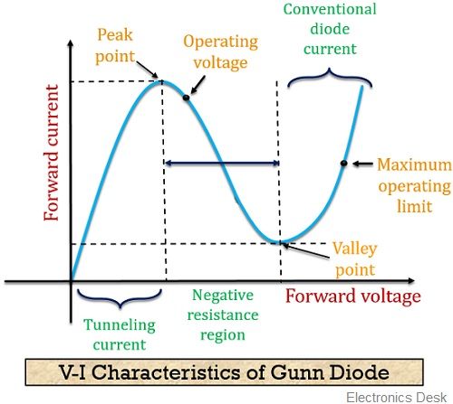
The current to the Gunn Diode will start to drop (negative resistance region) and the diode should start oscillating and the radar detector should alarm for K band.
The negative resistance region should be about 7 volts. As Fester has mentioned, if it goes above 8V you might have more than one broken diode.
The good news is that K band gunn diodes are relatively cheap and easy to source on ebay.
Yes I am an agent of Satan, but my duties are largely ceremonial.
So you think the low range issue could be from the gunn diode, or the zener that fester said? Can you tell which is the gunn and which is the schottky?
What's the voltage across the diode?
The only way you're going to know is first measure the in circuit voltage.
Then measure the current while you adjust the voltage from 5 to 8V
And while you have a K band radar detector looking for an output. A clear indication that the unit is actually working.
Once you have it working and all put back together, then you can address any range issues you might have.
I'd hate to think you pulled it all apart because you thought there was some gunn diode issue when instead it was something else like a receiver or power supply issue.
This is an exaggerated example of the Voltage vs Current curve you should see. If you don't see a negative resistance then the diode is most likely broken.
There are a number of other tests you can do, but they're all pointless if you don't do the basic checks first.
Yes I am an agent of Satan, but my duties are largely ceremonial.
I should clarify, which looking back at my first post I see that I didn't specify what was going on.
The unit I have functions, and quite well. It is very accurate as I have checked it against gps speed calculations, and other radar units.
The range actually seems quite good in my opinion, in stationary mode. However, when operating in moving mode, it seems the unit only picks up the echo signal very close to the target, sometimes it will miss the target completely.
It is entirely possible that this is just nature of it. However, seeing as it is a professionally built commercial police unit (albeit quite old), I would expect slightly higher range in moving mode. Especially when an oncoming vehicle is only, 15 meters away and it will completely miss it.
The manual claims that decreased range could be the result of a deteriorated schottky diode. I thought perhaps if someone was able to identify which component was the schottky diode, I could possibly locate one and replace it. I need some help identifying the component because there is also the Gunn diode in there.
I apologize for not specifying all this earlier. Thanks for everyone's help, I really appreciate it.
- Kyle
The schottky will be in the receiver circuit as overload protection - the zenner is to stop one dten ts trying to get more range by increasing the gunn diode voltage the gunn will be housed in a metal case to allow it to oscillate and to give direction to the output at a certain frequency and tuning ! some times they use another gunn to act as a detector and the difference in time is the doppler effect which makes the distance to the detected object calculatable by the electronics . almost all radar detectors can act as a transmitter if you find 5v and apply it to the gunn then tune it to confuse the one pointed at you the result is confusion of the doppler and they read fast like 999kmph . but you cant have them running continuously as they get hhhhooooot and ouchy poohs the smoke gets out
 Posting Permissions

 Reply With Quote
Bookmarks